|Table of Contents| Section Contents| Previous Section| Next Section|
The distribution of stress in a curved beam is determined by using the following assumptions:
1.  The cross section has an axis of symmetry in a plane
    along the length of the beam.
2.  The plane cross sections remain plane after bending.
3.  The modulus of elasticity is the same in tension
    as in compression.
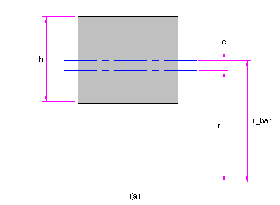
Unlike a straight beam, we shall find that the neutral axis and the centroidal axis of a curved beam are not coincident, and also that the stress does not vary linearly from the neutral axis. The notation shown in Figure 2-31 is defined as follows:
     r0 = radius of outer fiber
     ri = radius of inner fiber
     h = depth of section
     c0 = distance from neutral axis to outer fiber
     ci = distance from neutral axis to inner fiber
     r = radius of neutral axis
     rbar = radius of centroidal axis
     e = distance from centroidal axis to neutral axis
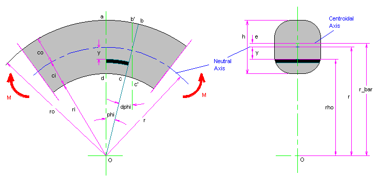
To begin, we define the element abcd by the angle phi. A bending moment M causes section bc to rotate through d phi to b'c'. The strain on any fiber at distance rho from the center O is
       epsilon = delta / l =
            (r-rho) * d phi / d rho                [a]
The normal stress corresponding to this stain is
       sigma = epsilon * E =
            E * (r-rho) * d phi / (rho * phi)      [b]
Since there are no axial external forces acting on the
beam, the sum of the normal forces acting on the
section must be zero. Therefore
       INTEGRAL(sigma * dA) = E * d phi / phi *
           (r-rho) * dA / rho = 0                  [c]
Now arrange equation [c] in the form
       E * d phi / phi * (r * INTEGRAL(dA/rho) -
           INTEGRAL(dA)) = 0                       [d]
and solve for the expression in parentheses. This gives
r * INTEGRAL(dA / rho) - A = 0
or
r = A / (INTEGRAL(dA / rho)) [2-70]
This important equation is used to find the location of
the neutral axis with respect to the center of curvature
O of the cross section. The equation indicates that the
neutral and the centroidal axes are not coincident.
Our next problem is to determine the stress distribution. We do this by balancing the external applied moment against the internal resisting moment. Thus, from equation [b],
     INTEGRAL((r-rho)*(sigma*dA)) =
        E*d phi / phi * INTEGRAL((r-rho)^2*dA / rho) =
           M
Since (r-rho)^2 = r^2 - 2*rho*r + rho^2, equation [e]
can be written in the form
     M = E * d phi / phi *
         (r^2*INTEGRAL(dA/rho)-r*INTEGRAL(dA)-
             r*INTEGRAL(dA)+INTEGRAL(rho * dA))       [f]
Note that r is constant; then compare the first two
terms in parentheses with equation [d]. These terms
vanish, and we have left
     M = E * d phi / phi *
          (-r*INTEGRAL(dA) + INTEGRAL(rho*dA))        [g]
The first integral in this expression is the area A,
and the second is the product rbar*A. Therefore
     M = E * d phi / phi * (rbar - r) * A
         = E * d phi / phi * e * A                    [h]
Now, using equation [b] once more, and rearranging,
we finally obtain
sigma = M * y / (A * e * (r-y)) [2-71]
This equation shows that the stress distribution is
hyperbolic. The maximum stresses occur at the
inner and outer fibers and are
     sigma_i = -M * ci / (A * e * ri)
     sigma_o = M * co / (A * e * ro)                 [2-72]
These equations are valid for pure bending. In the usual and
more general case, such as a crane hook, the U frame of a
press, or the frame of a clamp, the bending moment is due
to the forces acting to one side of the cross section under
consideration. In this case the bending moment is computed
about the centroidal axis, not the neutral axis.
Also, an additional axial tensile or compressive stress
must be added to the bending stress given by equations
[2-71] and [2-72] to obtain the resultant stress acting
on the section.
An optimum section for a curved beam can be designed by relating the inner and outer fiber stresses given by equation [2-72] in the same ration as the tensile and compressive strengths of the beam material. Thus, if the material is steel, the tensile and compressive strengths are nearly equal and we can design the section so that sigma_i = sigma_o and arrive at an optimum geometry. Note that this yields the simple relation
ci / co = ri / ro [i]
which, however, is not so simple to implement. An approach
to optimization is to decide on the form of the section
and to program equation [2-70] and other necessary
relations for digital computation. Then, using time
sharing with man-machine interaction, simply punch in
various trial values of the geometry until equation [i]
is satisfied. If batch processing is used, one of the
standard iteration techniques can be employed with
equation [i] as te STOP or END command.
Sections most frequently encountered in the stress analysis of curved beams are shown in Figure 2-32. Formulas for the rectangular section were developed in Example 2-11, but they are repeated here for convenience.
     rbar = ri + h/2                     [2-74]
     r = h / (ln(ro/ri))                 [2-75]
For the trapezoidal section in Figure 2-32b, the formulas are
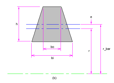
     rbar = ri + (h*(bi+2*bo))/(3*(bi+bo))        [2-76]
     r = A / (bo-bi+((bi*ro-bo*ri)/h)*ln(ro/ri))  [2-77]
For the T section in Figure 2-32c we have
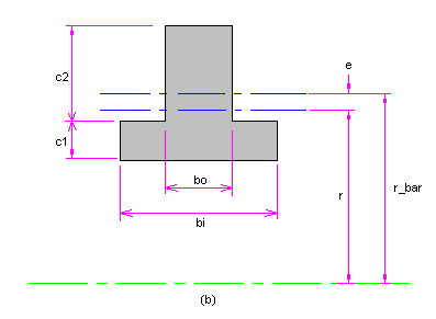
     rbar = ri + (bi*c1^2+2*bo*c1*c2+bo*c2^2) /
              (2*(bo*c2+bi*c1))                    [2-78]
     r = (bi*c1+bo*c2) /
            (bi*ln((ri+c1)/ri)+bo*ln(ro/(ri+c1)))  [2-79]
The equations for the solid round section of figure 3-32d are
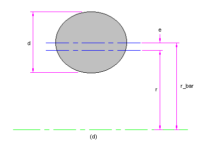
     rbar = ri + d / 2                          [2-80]
     r = d^2 / (4*(2*rbar-SQRT(4*rbar^2-d^2)))  [2-81]
Note, very particularly, that equation [2-81] gives the radius of curvature of the neutral axis. Do not confuse the result with the radius of the seciton!
The formulas for other sections can be obtained by performing the integration indicated in equation [2-70]. Cold forming of beams into curved beams introduces distortion of the seciton such that the resulting section has a different geometry than the unbent seciton. This distortion, of course, is greatest in the case of rectangular or circular tubing. For all these, as well as for complex sections, a numerical or graphical integration of equation [2-70] may be required if accurate results are desired.
This section of the book is UNDER CONSTRUCTION...